
This is part three in a series of articles on the ArduiNIX™. In this part we’ll begin taking a look at the hardware design and the performance of the high voltage power supply.
Schematic
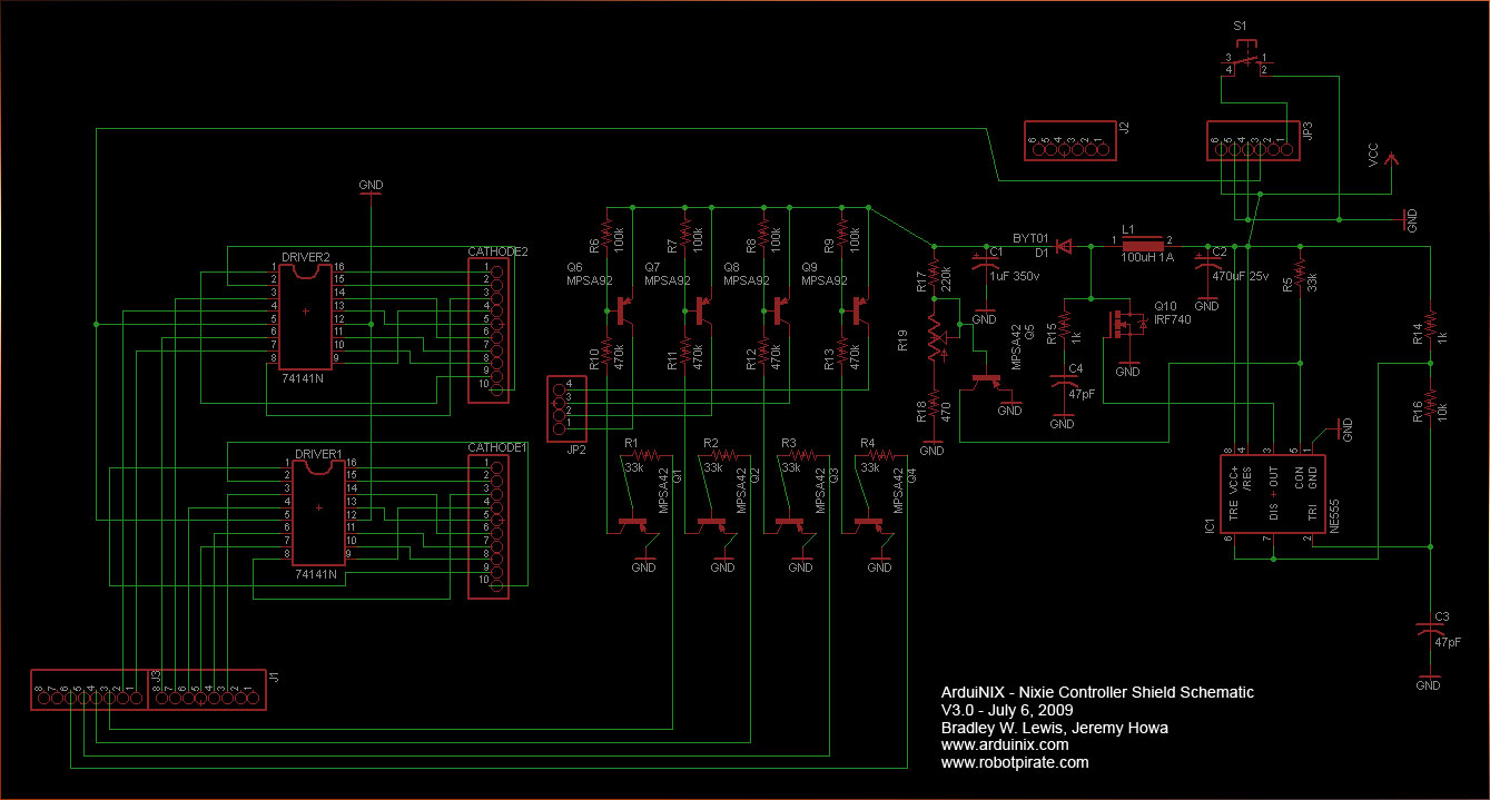
The ArduiNIX team has posted their design files online, including the schematic. See the forum post and then take a look at the schematic. Go ahead and take a look -- it's pretty simple. Open the schematic up in another browser tab so you can follow along.
It basically breaks down into three areas plus a bunch of connectors. Here’s an overview:

In this post, we’ll focus on the high voltage power supply. In the next one, we’ll address the anode and cathode drivers.
The high voltage power supply
The whole point of the ArduiNIX shield is to create and manage the high voltages needed to make nixie tubes work. The first challenge is how to generate high voltages (100v - 200v DC) from the battery-level voltages (5-12 v DC) available from the Arduino.
The high voltage power supply uses an oscillator, an inductor and a cap to pump the low input voltage from the Arduino up to the high voltage needed for the nixies. Basically, the 555-based oscillator switches the juice to an inductor (L1) on and off using Q10. Each time the inductor switches, its field reverses and that baby pumps a pulse of current into the cap at C1, raising the voltage across it far above the input voltage. Capacitor C3 sets the basic frequency of the oscillator and the circuit associated with high voltage transistor Q5 and trim pot at R19 feeds back the output voltage to fine-tune the oscillator to set the precise voltage. Thus, R19 allows you to adjust the output voltage to match your particular nixie tubes.
Switching noise
Now, all this oscillating and pulsing gets us the high voltage we need, but it also creates electrical noise. There isn’t a lot of noise with the ArduiNIX given the simplicity of the design and the low cost, but investigating it gave me a great excuse to hang out in my workshop and play with my oscilloscope. (And that’s all part of the fun, right?)
Here are two pictures of the signals, one at the low end of the range, one at the high end. I was using an 8.5v battery as external power to the Arduino in order to minimize the amount of noise coming into the system. The top trace (channel 1) on the scope is an AC-coupled view of the high voltage power (so we can focus on the tiny pulses on top of the large voltage), the middle trace (channel 2) is the 555 oscillator output so we can see how the noise correlates with the oscillator frequency, and the bottom trace (channel 3) is the “9v” pin on the top of the shield to give you an idea of what sort of noise the input voltage is carrying. Note that there is noise here, even with a battery. There’s noise everywhere!
Here’s the low end of the output range:

Here’s the top of the range (for this battery)

Notice two things: 1) the frequency changes with the voltage, and 2) the noise, directly related to the oscillation, increases with voltage.
Here’s a quick little video to see the changes in action:
Noise Spectrum
Let’s take a closer look at the pulse:

It’s a quick little fellow, and that means it has lots of high frequencies in it. Here’s a rough idea of the spectrum:

Watch out for line noise from external power supplies
Now, this is with a battery supply. When I use a wall wart, I get all sorts of 120Hz noise coming in from the rectified AC power. Notice in the following screen shots that the noise is coming in from the source supply (as shown on channel 3) but it gets amplified by the time it appears in the high voltage line (channel 1).
Low voltage:

High voltage (note how the high frequency switching noise is riding on top of the low frequency line noise):

And here’s a simple video:
Summary
Anyway, like I said earlier, this whole discussion of noise was really just an excuse to play with my oscilloscope. I don’t intend any disrespect to the ArduinNIX design or designers. It’s a very inexpensive design targeted at hobbyists like me and I love it. Further, I’m sure some of this noise is due to my setup: I haven’t been particularly careful about my cabling technique or my choice of wall wart.
But hopefully this discussion does indicate some notes for using the ArduiNIX:
- Simple switching high voltage power supplies like this generate electrical radio-frequency noise.
- This noise can be annoying to your neighbors, especially if they listen to AM talk radio or are radio amateurs.
- Keep all your cables short and put the system inside a shielded enclosure and it won’t be a problem.
- Invest in a well-filtered external power supply if you don’t want a lot of noise & ripple coming into the system.
- Use batteries for the lowest possible noise.
Finally, the good folks at RoboPirate have opened up the design so you can make any changes you like. If you have improvements, please give them back to the ArduiNIX community via the forums.
Next:
The next post will continue looking at the hardware design, focusing on the anode and cathode drivers used to multiplex the nixie tubes. Then we’ll start talking about how this multiplexing hardware design will guide your software design.
You have a slight error in your schematic: the MPSA42 is depicted as a PNP transistor rather than an NPN as it should be. The part number makes your intent clear, but you might want to make the schematic match your intentions more closely.
ReplyDeleteThanks! I'll pass your comment on to the ArduiNIX team. (I'm just a customer.)
ReplyDeleteLooking forward to your next update! Have you seen the new display boards?
ReplyDelete