Sunday, November 22, 2009

ArduiNIX™ - Part 4 - Multiplexing

This is part of a series on the ArduiNIX™ (http://arduinix.com), a sweet little Arduino shield. So far, we've covered
In this exciting episode, we’ll be continuing our tour of the ArduiNIX schematic, simplifying a bit so we can see how things are structured, heading towards our software design.

Keep those symbols simple

As we continue our tour, we’re going to use simplified symbols for the decoders and the Nixie tubes.

The Nixies I’m using have 10 cathodes (shaped like numerals) and a screen-like anode. These are old Russian IN-12A’s that I obtained from an excellent Ukrainian shop on eBay. Other Nixies might have more cathodes for a decimal point or other symbols (like the IN-12B shown below).


Since it’s not important to show which pins connect to which cathodes for the following diagrams, I’m going to show all the cathodes as one and just notate that there is a 10-line bus going into the tube.

Similarly, the 74141 or Russian equivalent decoder chip, which translates a four-bit nibble into one of ten output pins, will be shown as a simple rectangle with a four-line bus going in and a ten line bus coming out.

So, these are the symbols I'll be using:


Driving the series of tubes!

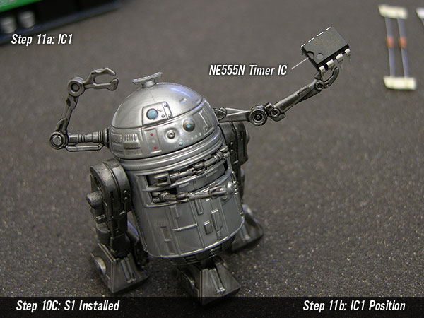
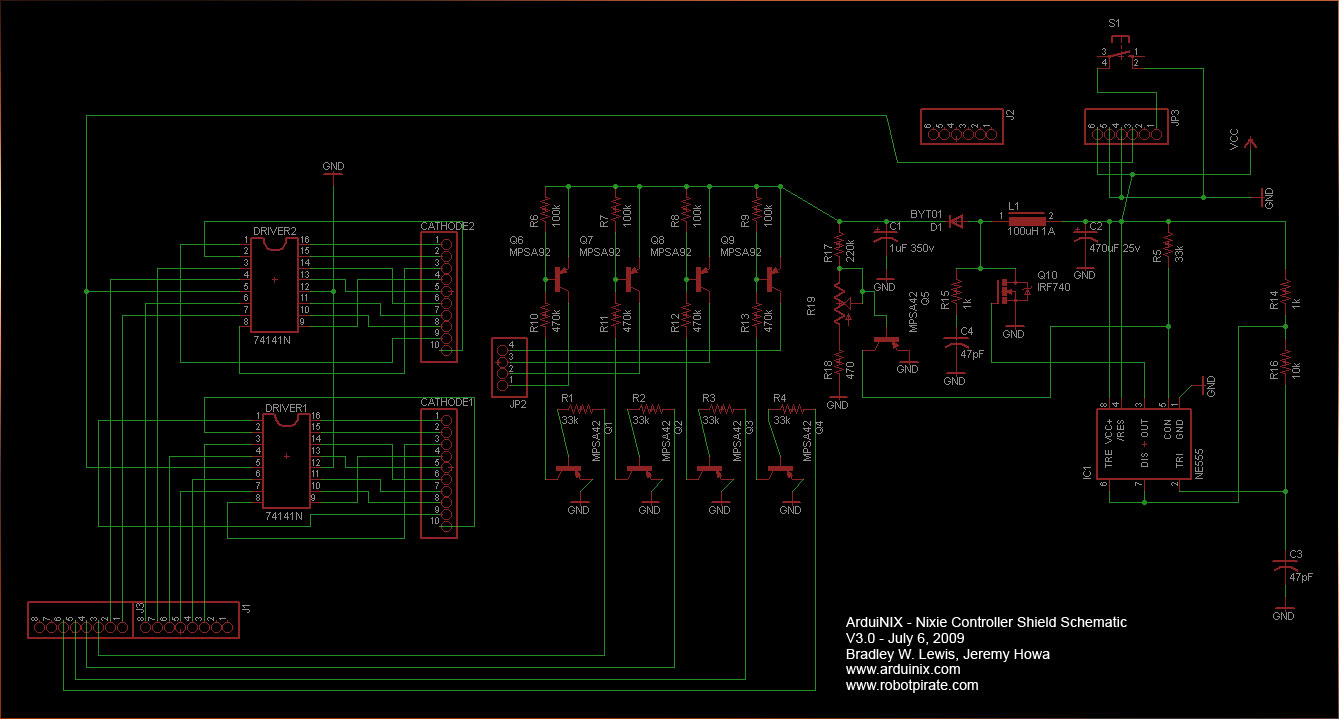
So, let’s dive into the schematic. (you can see a small copy here or at http://arduinix.com).  Now, as an alert reader pointed out, there’s a “typo” on the ArduniNIX schematic in the anode drivers – the MPSA42 is shown with a PNP symbol instead of the NPN device that it is. But don’t worry – the circuit actually works the right way. Here’s a simplified diagram of one anode driver circuit that shows the transistors but omits the biasing and current-limiting resistors.

When your software turns on the output pin to enable the anode, the MPSA42 at Q1 amplifies the microcontroller’s wimpy little output current and turns on the MPSA92 at Q6. These are high-voltage transistors and they are able to supply current to the Nixie tube at the high voltage it requires. It doesn’t need much current, only a few milliamps, so they don’t need to handle a lot of power. It’s the breakdown voltage that’s the important parameter.

Cathode driver

Now, I’ve shown the cathode side of the tube as going straight to ground. In reality, the circuit uses a 74141 high voltage decoder (or Russian K155N equivalent). This circuit converts four bits, presented simultaneously by four Arduino output pins, into one of ten output pins one at a time. It implements a table that looks something like this:


So, let’s put the anode driver circuit (represented now as just a box) and the cathode driver decoder chip together and see how the ArduiNIX connects to four tubes.


One tube at a time

You should only drive one tube at a time, for two reasons: 1) you don’t want to make the decoder pull too much current and exceed it’s maximum dissipation rating and 2) it’s boring to have all the tubes show the same numeral at the same time!

Instead, your software needs to drive just one tube at a time in a four step process:
  1. Set all four output pins (2 through 5) to have the decoder select one cathode
  2. Set just one of pins 10 through 13 to turn on just one anode of one tube
  3. Leave the tube on for a minimum length of time
  4. Turn that anode driver off before you go to the next tube.
The software switches from one tube to another quickly in a process called multiplexing. If you light up each tube faster than 20 or 30 times a second, they all appear to be on at the same time.

Wait for ionization

You have to pause on each tube and keep it lit for a millisecond or so. Nixies are slower than semiconductors. It can take from 10 mS up to 50 mS to get all those glowing ions moving from a cold start. Even after the tube is up and running, it can take at least a millisecond to light up the second cathode when you are switching from one cathode to another. So, your code needs to set the decoder, turn on the appropriate anode driver to light up the tube, and leave it that way for a relatively long time. Your code can go off and do other stuff while the tube stays lit, however, so there’s no worries.

On the positive side, Nixies stay lit for a similarly long time period (10 mS or more) after you remove the voltage, so this persistence works to our advantage during multiplexing.

The complete block diagram

The ArduiNIX includes two decoder chips, so the whole schematic (except for the high voltage power supply) boils down to this:


The same principle applies, but we can light up two tubes at once and cycle through all four pairs as fast as possible.

Simplified multiplexing code

The code (again, simplified and squeezed to fit on the blog) might look something like this:

// Variables

// first, keep the numerals in an array
byte NumberArray[8]={0,0,0,0,0,0,0,0};
const byte numberOfPairs = sizeof(NumberArray)/2;

// Set the minimum time to keep a tube lit
const byte MinimumNixieDelay=5; 

// Remember when we can light up the next tube pair.
// This needs to be big to reduce rollover problems
unsigned long TimeForNextNixie; 

// Keep track of which pair of tubes are lit                                
int tubePair;

// setup code omitted for brevity

void loop()  // Arduino main loop   
{
  // loop through all the pairs of nixie tubes
  for (tubePair=0; 
       tubePair < numberOfPairs; 
       tubePair++) {
 
     // light up a pair of tubes and leave them lit
     DisplayNumberPair(tubePair,
                       NumberArray[tubePair],
                       NumberArray[(tubePair+4)]);
   
     // Set the future time to light the next pair 
     TimeForNextNixie = millis() + MinimumNixieDelay; 
   
    // use the time while the tubes are lighting up
    // to do other stuff 
    OtherStuff();
 
    // Finally we wait in case we still 
    // have time left in the minimum interval. 
    while (millis() < TimeForNextNixie ) {
     delay(1);
    }
  } // end of for loop
} 
My demo hardware arranges the tubes in a line exactly like this, so you can see the multiplexing in action in the following short video. Notice how some frames show one pair lighting up while the previous one is still glowing. This is the persistence I mentioned earlier. When I speed up the multiplexing rate, it looks like all the tubes are on simultaneously. You may notice a little flickering. I think this is a combination of several factors: the multiplexing itself, the interaction between the frame rate of the transcoded video and the multiplexing rate, and the tube’s natural variations. It’s visible in person, not just on a recorded video. In the end, I like the effect. It’s all part of the overall tubalicious Nix-a-esthetic!
Next time

Next time, we’ll take a look at your options for cabling up your tubes, and then we’ll look closer at the software.

Sunday, November 1, 2009

ArduiNIX™ - Part 3 - The high voltage power supply


This is part three in a series of articles on the ArduiNIX™. In this part we’ll begin taking a look at the hardware design and the performance of the high voltage power supply.


Schematic

The ArduiNIX team has posted their design files online, including the schematic. See the forum post and then take a look at the schematic. Go ahead and take a look -- it's pretty simple. Open the schematic up in another browser tab so you can follow along.

It basically breaks down into three areas plus a bunch of connectors. Here’s an overview:


In this post, we’ll focus on the high voltage power supply. In the next one, we’ll address the anode and cathode drivers.

The high voltage power supply

The whole point of the ArduiNIX shield is to create and manage the high voltages needed to make nixie tubes work. The first challenge is how to generate high voltages (100v - 200v DC) from the battery-level voltages (5-12 v DC) available from the Arduino.

The high voltage power supply uses an oscillator, an inductor and a cap to pump the low input voltage from the Arduino up to the high voltage needed for the nixies. Basically, the 555-based oscillator switches the juice to an inductor (L1) on and off using Q10. Each time the inductor switches, its field reverses and that baby pumps a pulse of current into the cap at C1, raising the voltage across it far above the input voltage. Capacitor C3 sets the basic frequency of the oscillator and the circuit associated with high voltage transistor Q5 and trim pot at R19 feeds back the output voltage to fine-tune the oscillator to set the precise voltage. Thus, R19 allows you to adjust the output voltage to match your particular nixie tubes.

Switching noise

Now, all this oscillating and pulsing gets us the high voltage we need, but it also creates electrical noise. There isn’t a lot of noise with the ArduiNIX given the simplicity of the design and the low cost, but investigating it gave me a great excuse to hang out in my workshop and play with my oscilloscope. (And that’s all part of the fun, right?)

Here are two pictures of the signals, one at the low end of the range, one at the high end. I was using an 8.5v battery as external power to the Arduino in order to minimize the amount of noise coming into the system. The top trace (channel 1) on the scope is an AC-coupled view of the high voltage power (so we can focus on the tiny pulses on top of the large voltage), the middle trace (channel 2) is the 555 oscillator output so we can see how the noise correlates with the oscillator frequency, and the bottom trace (channel 3) is the “9v” pin on the top of the shield to give you an idea of what sort of noise the input voltage is carrying. Note that there is noise here, even with a battery. There’s noise everywhere!

Here’s the low end of the output range:


Here’s the top of the range (for this battery)


Notice two things: 1) the frequency changes with the voltage, and 2) the noise, directly related to the oscillation, increases with voltage.

Here’s a quick little video to see the changes in action:


Noise Spectrum

Let’s take a closer look at the pulse:


It’s a quick little fellow, and that means it has lots of high frequencies in it. Here’s a rough idea of the spectrum:


In this picture, the main frequency is at top left. The noise spectrum drops off (5 dB per vertical division) as the frequency increases (12.5 MHz per horizontal division). You can see that there is noise (albeit 20 to 30 dB down) up far up into the radio spectrum. Don’t pay too much attention to the details of this plot – especially above 75 MHz. I wasn’t particularly careful with my probe technique and the little scope only has a 100 MHz bandwidth so there are lots of measurement errors and alias artifacts. The bottom line is that there is some noise far into the radio spectrum due to these little pulses.

Watch out for line noise from external power supplies

Now, this is with a battery supply. When I use a wall wart, I get all sorts of 120Hz noise coming in from the rectified AC power. Notice in the following screen shots that the noise is coming in from the source supply (as shown on channel 3) but it gets amplified by the time it appears in the high voltage line (channel 1).

Low voltage:


High voltage (note how the high frequency switching noise is riding on top of the low frequency line noise):


And here’s a simple video:


Summary

Anyway, like I said earlier, this whole discussion of noise was really just an excuse to play with my oscilloscope. I don’t intend any disrespect to the ArduinNIX design or designers. It’s a very inexpensive design targeted at hobbyists like me and I love it. Further, I’m sure some of this noise is due to my setup: I haven’t been particularly careful about my cabling technique or my choice of wall wart.

But hopefully this discussion does indicate some notes for using the ArduiNIX:

  1. Simple switching high voltage power supplies like this generate electrical radio-frequency noise.
  2. This noise can be annoying to your neighbors, especially if they listen to AM talk radio or are radio amateurs.
  3. Keep all your cables short and put the system inside a shielded enclosure and it won’t be a problem.
  4. Invest in a well-filtered external power supply if you don’t want a lot of noise & ripple coming into the system.
  5. Use batteries for the lowest possible noise.

Finally, the good folks at RoboPirate have opened up the design so you can make any changes you like. If you have improvements, please give them back to the ArduiNIX community via the forums.

Next:

The next post will continue looking at the hardware design, focusing on the anode and cathode drivers used to multiplex the nixie tubes. Then we’ll start talking about how this multiplexing hardware design will guide your software design.

Wednesday, October 21, 2009

ArduiNIX™ - Part 2 - Building the kit

This is a series of articles on the ArduiNIX™ board from RoboPirate. (Here's a link to Part 1.) This segment is on building the kit.

Wonderful, funny directions
I’ve been putting together electronics kits a long time - since I built my dad a Heathkit vacuum tube voltmeter in the late sixties. Good instructions go a long way towards making the build an easy, trouble-free experience. The ArduiNIX instructions are clear, well-illustrated, and quite useful for the beginner. But they go beyond that. As an experienced constructionist, the instructions in this kit are the first that I would actually call fun to the point of whimsy. I mean, look at this picture:


(http://www.arduinix.com/Main/AssemblyHTML/11a.html - Used by permission.)


That droid is heroic! I laughed more during this build than any other I have ever done. Take your time and have some fun.

It is a good idea to read through the entire set of instructions while you are waiting for your kit to be delivered. Not only is it a fun read, but there are a few choices you can make along the way to customize the kit and you might want to collect some alternate components.

Some confusion on C3
I was a little confused about the C3 capacitor. This cap helps determine the maximum high voltage output, so you can modify it to adapt the high voltage power to your particular type of nixie tube or vacuum florescent tube. The online instructions available when I built my kit did not quite match the component included with the kit. But, if you pay attention, you won’t have any problems.

Excellent customer support
The design team has been tweaking the C3 cap to improve the performance of the high voltage power supply. This was why the C3 that came with the kit was a better one that their instructions showed.  It worked fine for my application, but I got a pleasant surprise a month or two after I bought the kit. The design team came up with an even better choice of cap and sent it out to anybody who asked, free of charge.


While it’s typical to get software upgrades from companies, this was the first time I’ve ever gotten a component upgrade. It’s a small thing but, like the whimsical instructions, it is one of the things that made this kit a delight to own.

Optional choice of header
Their instructions discuss some possible variations of header choice for the cathode connections. The vertical one supplied with the kit worked for me because I was planning on recycling some old disk ribbon cables. (More about this later.) But you might want to substitute an angle connector to keep the profile lower.

High voltage header
Be careful with your choice of high voltage header for the four anode connections. (You don’t need to worry about the cathode connections because they stay at or near ground potential.) This area of the board supplies voltages up to 250v DC and, even though the currents are low, it would still be very nasty for you to touch or to have one of your prototyping jumpers touch the wrong pin.  I used the supplied header and a relatively open (but insulated) cabling scheme for my prototyping but I intend to replace this with an interlocking connector designed for high voltage safety when the design stabilizes.


For this same reason, be very careful about the underside of the board where there are a few high voltage signal lines. Check to make sure there is nothing touching the Arduino board below.

Custom headers
Finally, I used a set of stacking headers for the pins connecting to the underlying Arduino board. Due to the component height on the ArduiNIX, it has to be on the top of the stack, but this scheme allows me to use jumper cables for prototyping. You can get these at Sparkfun (http://www.sparkfun.com/commerce/product_info.php?products_id=9279) or other component supplier. I had some long ones in my parts drawer that I hacked to size.


Summary
In summary, this is an easy kit to build and the instructions make the process a wonderfully fun experience. The company is a delight to work with. Spend some time thinking about how you want to use the board before you install your headers, and pay careful attention to C3.

Next:
Next, we’ll take a look at the electrical design: perusing the circuit schematic, understanding how the hardware design influences your software options, and checking on the performance of the high voltage power supply.

Monday, October 12, 2009

ArduiNIX™ - Part 1


Back somewhere in the seventies, a high school science club took a field trip to a local laboratory. Somewhere during the tour, a young nerd found himself fascinated by an expensive frequency counter mounted in a rack. Instead of the analog meters in the frequency meters back at school, this one had glowing numbers! They were accurate to a single hertz and were changing as fast as the signal changed. It was wonderful! These digits, built from “nixie” tubes, were much faster and cheaper than mechanical numerals being used in the digital clocks, airplane cockpits, NASA consoles and space capsules of the day.

Nixie tubes were my first taste of the future. At the time, they were a bridge between the vacuum tubes of the last generation and the digital circuitry that was just becoming mainstream. These days they are no longer made in large quantities, but nixies of all varieties can be hunted down in surplus supply stores and are plentiful on eBay, shipped from old stock still available in Eastern Europe. Depending on the model, they are cheap, too.

For more information on nixie tubes, start at the Wikipedia article.

Nixie tubes have an esoteric niche in the modern DIY electronics milieu. Though definitely retro, they are too modern to fit in to the analog aesthetic of steampunk (for a marvelous example, see this wonderful steampunk/art deco Chronulator). Moreover, nixies require high voltage circuitry that can make them a challenge to interface with modern low-voltage electronics.


Now, with the availability of the ArduiNIX™ kit from Jeremy Howa and Bradley Lewis of RoboPirate, interfacing to nixie tubes is fun and easy. The ArduiNIX provides all you need to interface between an Arduino and up to eight nixie tubes of any variety. It includes its own high voltage power supply and interfacing circuitry and all fits neatly into a standard Arduino shield form factor.

In the next series of articles, we’ll go through the absolutely joyful process of building this kit, look into the circuit design, prototype up an eight digit nixie tube display, and write a few software routines to display interesting information and make the digits dance.

Oh, and sorry - there won’t be any clocks. With a clock in every phone, appliance, and trinket, the world doesn’t need any more clocks. Not even if they incorporate those fascinating, glowing, delightful digits of yore. Let’s see what else might be possible.